Abs Trailer Wiring Diagram
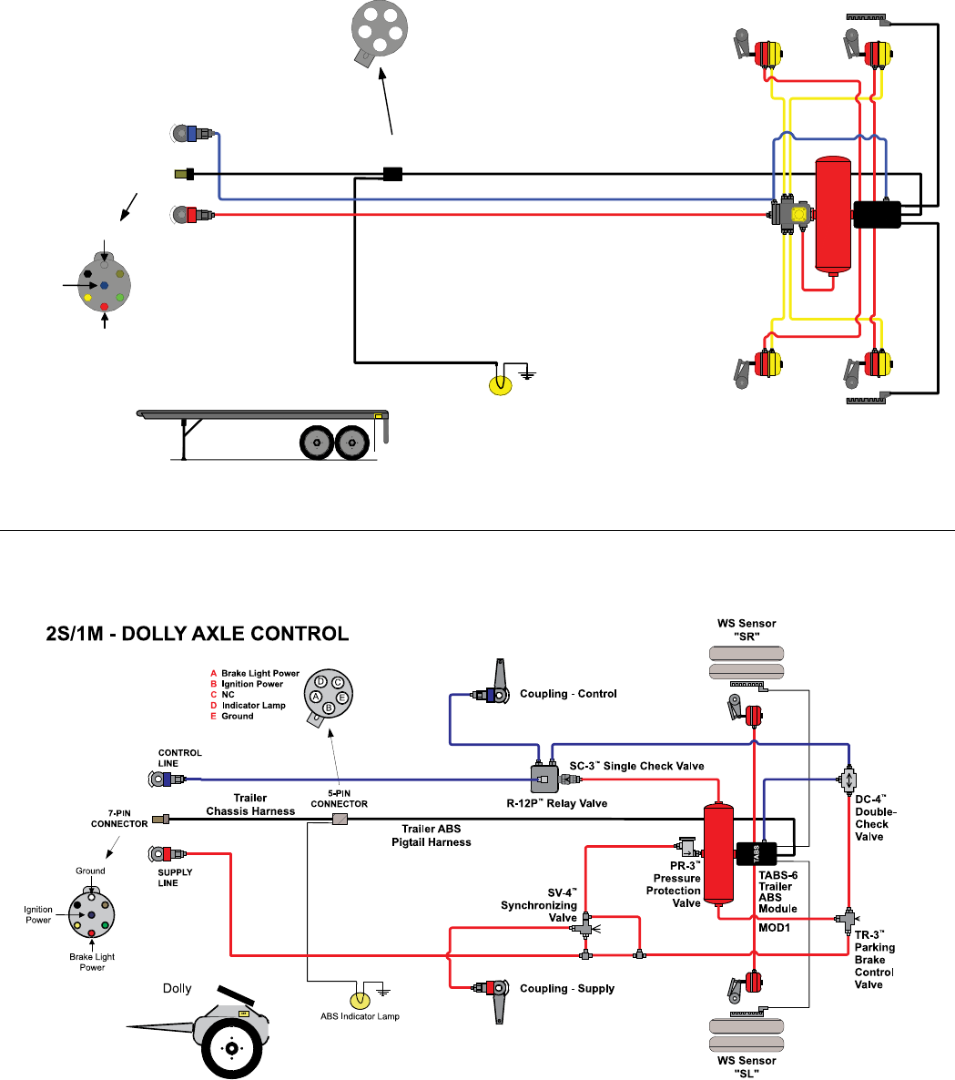
Abs Trailer Wiring Diagram - The wiring diagram for a semi trailer with abs includes various components such as the abs control module, wheel speed sensors, and. Recommended locations are shown in figures. Sensor (1a) should be installed on curb side. Sensor (1b) should be installed on road side. A haldex trailer abs wiring diagram is a schematic representation of the electrical connections between the various components.
Sensor (1b) should be installed on road side. The wiring diagram for a semi trailer with abs includes various components such as the abs control module, wheel speed sensors, and. A haldex trailer abs wiring diagram is a schematic representation of the electrical connections between the various components. Recommended locations are shown in figures. Sensor (1a) should be installed on curb side.
Sensor (1b) should be installed on road side. The wiring diagram for a semi trailer with abs includes various components such as the abs control module, wheel speed sensors, and. A haldex trailer abs wiring diagram is a schematic representation of the electrical connections between the various components. Recommended locations are shown in figures. Sensor (1a) should be installed on curb side.
![[DIAGRAM] Meritor Wabco Trailer Abs Wiring Diagrams](https://sc02.alicdn.com/kf/HTB1vS.3KpXXXXXHXpXXq6xXFXXX7/ABS-ELECTRIC-CONFIGURATION-2S-2M-MERITOR-WABCO.jpg)
[DIAGRAM] Meritor Wabco Trailer Abs Wiring Diagrams
A haldex trailer abs wiring diagram is a schematic representation of the electrical connections between the various components. Sensor (1a) should be installed on curb side. Recommended locations are shown in figures. Sensor (1b) should be installed on road side. The wiring diagram for a semi trailer with abs includes various components such as the abs control module, wheel speed.

Semi Trailer Abs Wiring Diagram Wiring Diagram
The wiring diagram for a semi trailer with abs includes various components such as the abs control module, wheel speed sensors, and. Recommended locations are shown in figures. A haldex trailer abs wiring diagram is a schematic representation of the electrical connections between the various components. Sensor (1b) should be installed on road side. Sensor (1a) should be installed on.

7way Semi Trailer Plug Wiring Diagram With Abs
Sensor (1a) should be installed on curb side. The wiring diagram for a semi trailer with abs includes various components such as the abs control module, wheel speed sensors, and. Recommended locations are shown in figures. A haldex trailer abs wiring diagram is a schematic representation of the electrical connections between the various components. Sensor (1b) should be installed on.

Wabco Trailer Abs Module Wiring Diagram DevLog Complete Information
A haldex trailer abs wiring diagram is a schematic representation of the electrical connections between the various components. Recommended locations are shown in figures. Sensor (1a) should be installed on curb side. Sensor (1b) should be installed on road side. The wiring diagram for a semi trailer with abs includes various components such as the abs control module, wheel speed.

Understanding ABS Wiring in Semi Trailers A Simplified Diagram
Sensor (1b) should be installed on road side. A haldex trailer abs wiring diagram is a schematic representation of the electrical connections between the various components. Recommended locations are shown in figures. Sensor (1a) should be installed on curb side. The wiring diagram for a semi trailer with abs includes various components such as the abs control module, wheel speed.

A Complete Guide to Understanding Semi Trailer ABS Wiring Diagrams
A haldex trailer abs wiring diagram is a schematic representation of the electrical connections between the various components. Sensor (1b) should be installed on road side. Recommended locations are shown in figures. The wiring diagram for a semi trailer with abs includes various components such as the abs control module, wheel speed sensors, and. Sensor (1a) should be installed on.
Haldex Trailer Abs Module Wiring Diagram at Jacob Lutz blog
Recommended locations are shown in figures. Sensor (1a) should be installed on curb side. The wiring diagram for a semi trailer with abs includes various components such as the abs control module, wheel speed sensors, and. Sensor (1b) should be installed on road side. A haldex trailer abs wiring diagram is a schematic representation of the electrical connections between the.

Wabco Trailer Abs Wiring Diagram
The wiring diagram for a semi trailer with abs includes various components such as the abs control module, wheel speed sensors, and. A haldex trailer abs wiring diagram is a schematic representation of the electrical connections between the various components. Sensor (1a) should be installed on curb side. Sensor (1b) should be installed on road side. Recommended locations are shown.

A Complete Guide to Understanding Semi Trailer ABS Wiring Diagrams
Sensor (1a) should be installed on curb side. Sensor (1b) should be installed on road side. Recommended locations are shown in figures. A haldex trailer abs wiring diagram is a schematic representation of the electrical connections between the various components. The wiring diagram for a semi trailer with abs includes various components such as the abs control module, wheel speed.

Ultimate Guide to Wabco Trailer ABS Wiring Diagram
The wiring diagram for a semi trailer with abs includes various components such as the abs control module, wheel speed sensors, and. Sensor (1b) should be installed on road side. Recommended locations are shown in figures. Sensor (1a) should be installed on curb side. A haldex trailer abs wiring diagram is a schematic representation of the electrical connections between the.
Recommended Locations Are Shown In Figures.
The wiring diagram for a semi trailer with abs includes various components such as the abs control module, wheel speed sensors, and. Sensor (1a) should be installed on curb side. A haldex trailer abs wiring diagram is a schematic representation of the electrical connections between the various components. Sensor (1b) should be installed on road side.