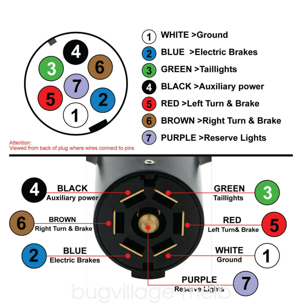
Trailer Plug Diagram 7 Pin
Trailer Plug Diagram 7 Pin - Pin number one (top left) usually manages the left turn indicator, while pin number four (top right) is commonly designated for the right turn. Not only do they provide the required running lights, turn. This is the most common (standard) wiring scheme for rv plugs and the one used by major auto manufacturers today.
This is the most common (standard) wiring scheme for rv plugs and the one used by major auto manufacturers today. Not only do they provide the required running lights, turn. Pin number one (top left) usually manages the left turn indicator, while pin number four (top right) is commonly designated for the right turn.
Not only do they provide the required running lights, turn. Pin number one (top left) usually manages the left turn indicator, while pin number four (top right) is commonly designated for the right turn. This is the most common (standard) wiring scheme for rv plugs and the one used by major auto manufacturers today.

Seven Way Trailer Connector Diagram 7 Pin Trailer Plug Wirin
Pin number one (top left) usually manages the left turn indicator, while pin number four (top right) is commonly designated for the right turn. This is the most common (standard) wiring scheme for rv plugs and the one used by major auto manufacturers today. Not only do they provide the required running lights, turn.
Seven Way Rv Plug Wiring Diagram 7 Pin Rv Plug Wiring Diagra
Pin number one (top left) usually manages the left turn indicator, while pin number four (top right) is commonly designated for the right turn. This is the most common (standard) wiring scheme for rv plugs and the one used by major auto manufacturers today. Not only do they provide the required running lights, turn.
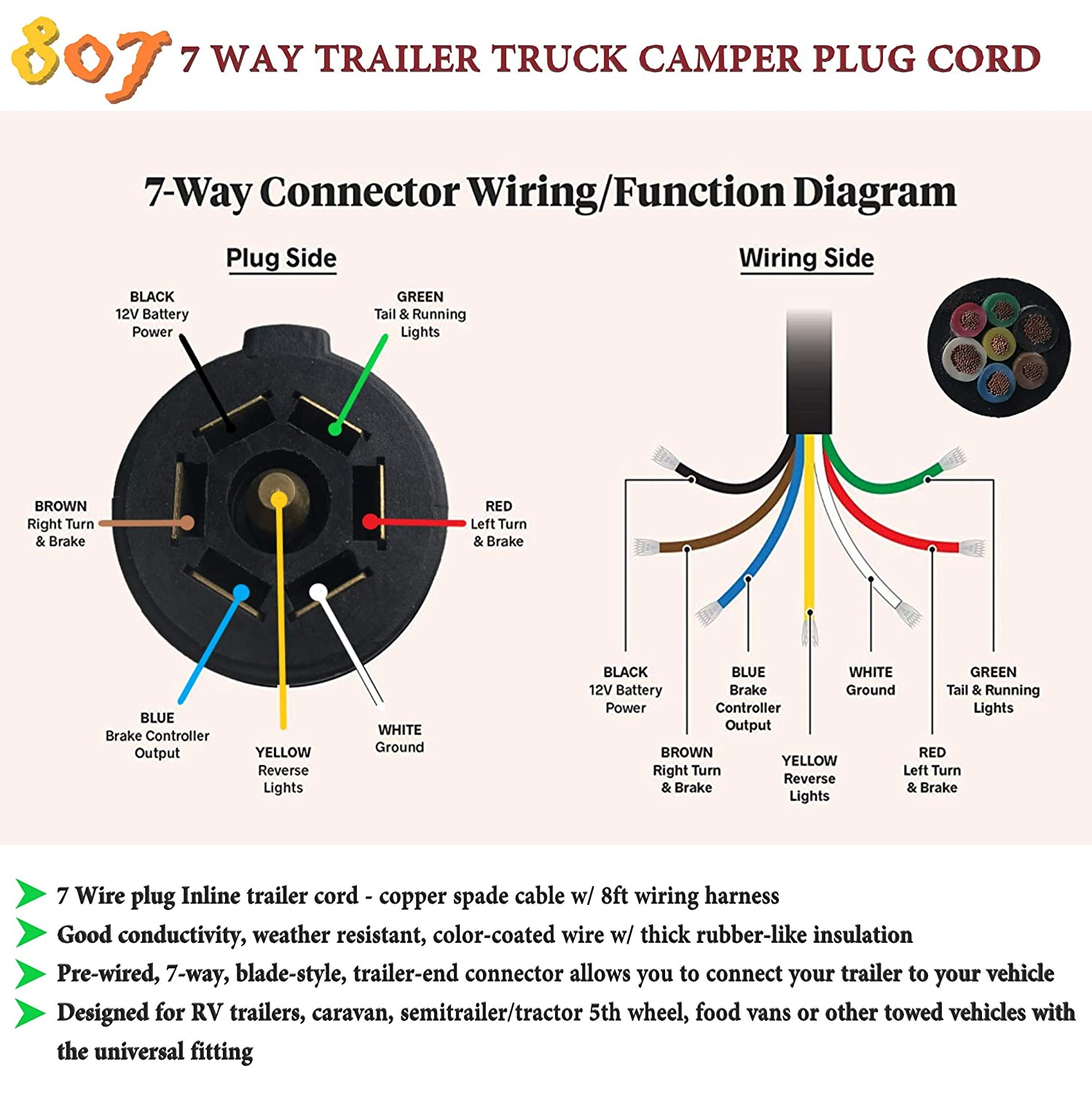
Trailer Plug Wiring Diagram 7 Way
This is the most common (standard) wiring scheme for rv plugs and the one used by major auto manufacturers today. Pin number one (top left) usually manages the left turn indicator, while pin number four (top right) is commonly designated for the right turn. Not only do they provide the required running lights, turn.

Demystifying the 7 Pin Flat Trailer Plug Wiring Diagram A StepbyStep
This is the most common (standard) wiring scheme for rv plugs and the one used by major auto manufacturers today. Pin number one (top left) usually manages the left turn indicator, while pin number four (top right) is commonly designated for the right turn. Not only do they provide the required running lights, turn.

How to Wire a 7 Pin Plug for Your Trailer StepbyStep Diagram Guide
This is the most common (standard) wiring scheme for rv plugs and the one used by major auto manufacturers today. Pin number one (top left) usually manages the left turn indicator, while pin number four (top right) is commonly designated for the right turn. Not only do they provide the required running lights, turn.

7 Way Trailer Plug Wiring Diagram With Brakes Circuit Diagram
Pin number one (top left) usually manages the left turn indicator, while pin number four (top right) is commonly designated for the right turn. Not only do they provide the required running lights, turn. This is the most common (standard) wiring scheme for rv plugs and the one used by major auto manufacturers today.

7 Way Semi Trailer Plug Diagram 7 Pin Trailer Plug Wiring Co
Pin number one (top left) usually manages the left turn indicator, while pin number four (top right) is commonly designated for the right turn. Not only do they provide the required running lights, turn. This is the most common (standard) wiring scheme for rv plugs and the one used by major auto manufacturers today.
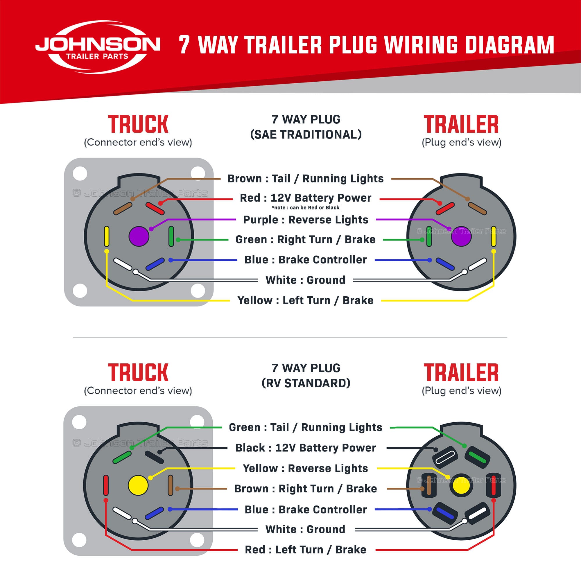
How to Wire a 7 Way Trailer Plug & Trailer Johnson Trailer Parts
Pin number one (top left) usually manages the left turn indicator, while pin number four (top right) is commonly designated for the right turn. This is the most common (standard) wiring scheme for rv plugs and the one used by major auto manufacturers today. Not only do they provide the required running lights, turn.

How to Wire a 7 Pin Plug for Your Trailer StepbyStep Diagram Guide
This is the most common (standard) wiring scheme for rv plugs and the one used by major auto manufacturers today. Not only do they provide the required running lights, turn. Pin number one (top left) usually manages the left turn indicator, while pin number four (top right) is commonly designated for the right turn.
Trailer Plug Wiring Diagram 7 Pin Flat 7 Way Trailer Plug
This is the most common (standard) wiring scheme for rv plugs and the one used by major auto manufacturers today. Pin number one (top left) usually manages the left turn indicator, while pin number four (top right) is commonly designated for the right turn. Not only do they provide the required running lights, turn.
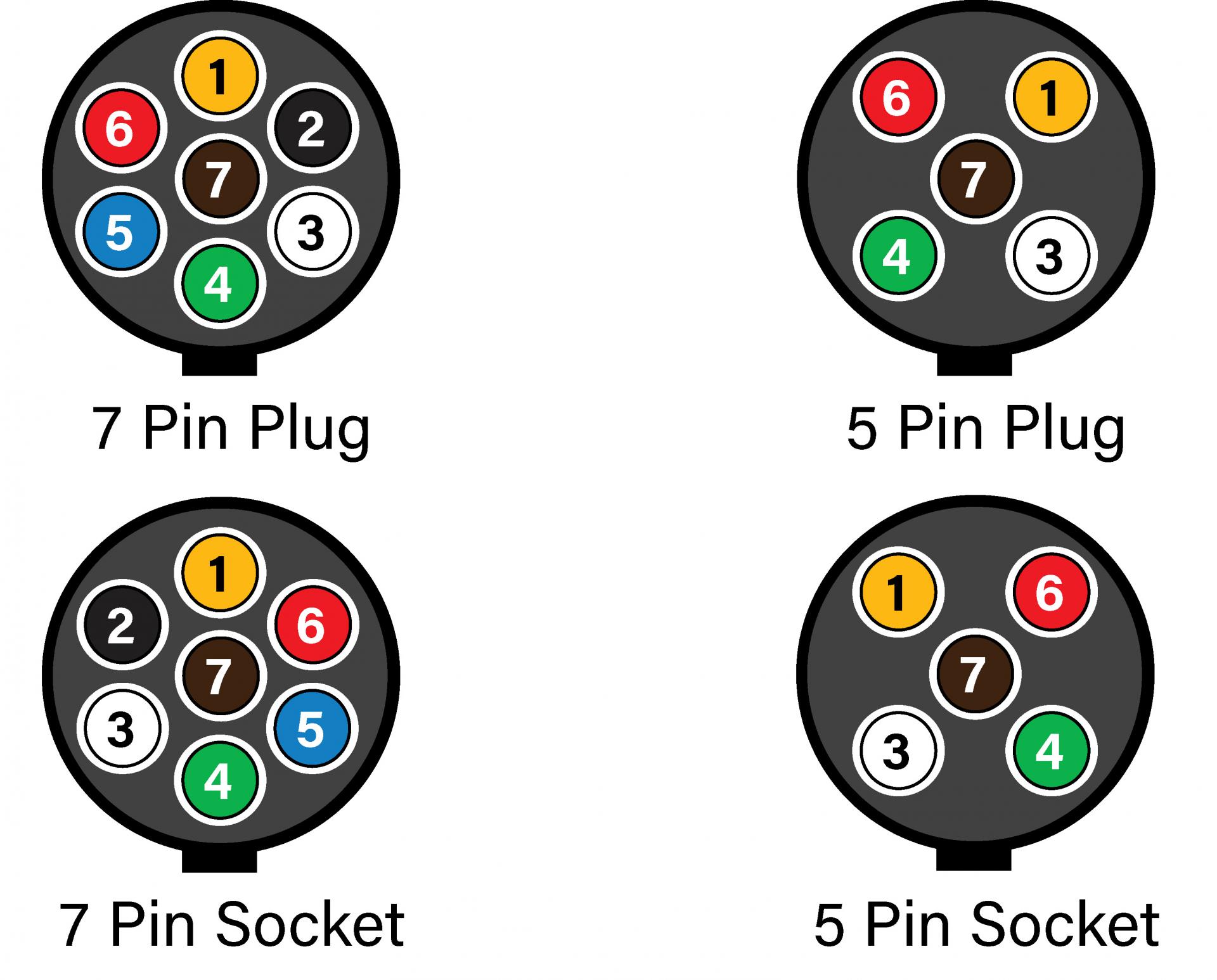
Pin Number One (Top Left) Usually Manages The Left Turn Indicator, While Pin Number Four (Top Right) Is Commonly Designated For The Right Turn.
This is the most common (standard) wiring scheme for rv plugs and the one used by major auto manufacturers today. Not only do they provide the required running lights, turn.