Wiring Diagram For 7 Pin Trailer
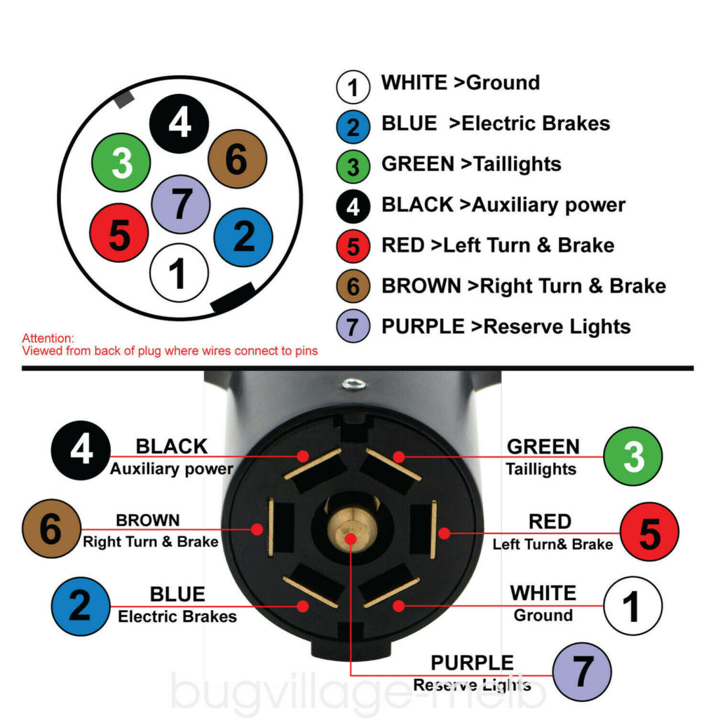
Wiring Diagram For 7 Pin Trailer - This is the most common (standard) wiring scheme for rv plugs and the one used by major auto manufacturers today. Pin number one (top left) usually manages the left. Use a multimeter to verify each terminal’s output before making permanent connections.
Pin number one (top left) usually manages the left. This is the most common (standard) wiring scheme for rv plugs and the one used by major auto manufacturers today. Use a multimeter to verify each terminal’s output before making permanent connections.
Pin number one (top left) usually manages the left. This is the most common (standard) wiring scheme for rv plugs and the one used by major auto manufacturers today. Use a multimeter to verify each terminal’s output before making permanent connections.
7 Pin Trailer Plug Wiring Diagram Australia Camp Trailer Plu
Pin number one (top left) usually manages the left. This is the most common (standard) wiring scheme for rv plugs and the one used by major auto manufacturers today. Use a multimeter to verify each terminal’s output before making permanent connections.
Wiring Diagram For 7 Pin Trailer Lights at Bernard Knorr blog
This is the most common (standard) wiring scheme for rv plugs and the one used by major auto manufacturers today. Use a multimeter to verify each terminal’s output before making permanent connections. Pin number one (top left) usually manages the left.

7 Way Trailer Plug Wiring Diagram With Brakes Circuit Diagram
This is the most common (standard) wiring scheme for rv plugs and the one used by major auto manufacturers today. Use a multimeter to verify each terminal’s output before making permanent connections. Pin number one (top left) usually manages the left.

Demystifying the 7 Pin Flat Trailer Plug Wiring Diagram A StepbyStep
Pin number one (top left) usually manages the left. Use a multimeter to verify each terminal’s output before making permanent connections. This is the most common (standard) wiring scheme for rv plugs and the one used by major auto manufacturers today.

7 Way Semi Trailer Plug Diagram 7 Pin Trailer Plug Wiring Co
Pin number one (top left) usually manages the left. Use a multimeter to verify each terminal’s output before making permanent connections. This is the most common (standard) wiring scheme for rv plugs and the one used by major auto manufacturers today.

How to Wire a 7 Pin Plug for Your Trailer StepbyStep Diagram Guide
Pin number one (top left) usually manages the left. Use a multimeter to verify each terminal’s output before making permanent connections. This is the most common (standard) wiring scheme for rv plugs and the one used by major auto manufacturers today.

The Ultimate Guide to Trailer Plug Wiring Diagrams 7 Pin
This is the most common (standard) wiring scheme for rv plugs and the one used by major auto manufacturers today. Pin number one (top left) usually manages the left. Use a multimeter to verify each terminal’s output before making permanent connections.

Wire Diagram for 7 Pin Trailer Plug Ultimate Guide & Tips Go Carlife
Use a multimeter to verify each terminal’s output before making permanent connections. This is the most common (standard) wiring scheme for rv plugs and the one used by major auto manufacturers today. Pin number one (top left) usually manages the left.
How To Connect Your 7 Pin Trailer Wiring Easily (Diagram Included
This is the most common (standard) wiring scheme for rv plugs and the one used by major auto manufacturers today. Pin number one (top left) usually manages the left. Use a multimeter to verify each terminal’s output before making permanent connections.
Wire Diagram for 7 Pin Trailer Plug Ultimate Guide & Tips Go Carlife
Pin number one (top left) usually manages the left. Use a multimeter to verify each terminal’s output before making permanent connections. This is the most common (standard) wiring scheme for rv plugs and the one used by major auto manufacturers today.
This Is The Most Common (Standard) Wiring Scheme For Rv Plugs And The One Used By Major Auto Manufacturers Today.
Use a multimeter to verify each terminal’s output before making permanent connections. Pin number one (top left) usually manages the left.